Antenna Technology Topics for CableFree MIMO Radio Links
 This technology paper contains explanations of key terms related to Antenna technology. Selection of the right antenna is key to ensure successful design and implementation of a Wireless Network. Our goal is to ensure you can understand and choose the correct CableFree antenna for your application – if in doubt, please Contact Us and our team of experts will guide you to ensure you have the correct antennas.
Antenna Gain

An antenna’s gain is a critical performance metric which reflects its directivity and electrical efficiency.
For a transmitting antenna, gain indicates how effectively it converts input power into radio waves directed towards a specific direction. For a receiving antenna, it shows how well it converts incoming radio waves from a specific direction into electrical power. When no direction is specified, “gain” refers to the peak gain value. The gain’s variation with direction is depicted in the antenna’s radiation pattern.
Antenna gain is defined as the ratio of power produced by the antenna along its beam axis from a far-field source to the power produced by a hypothetical lossless isotropic antenna, which receives signals equally from all directions. This ratio is expressed in decibels, termed “decibels-isotropic” (dBi). Alternatively, gain can be compared to a lossless half-wave dipole antenna, with units in dBd. Since a lossless dipole has a gain of 2.15 dBi, the relationship is: gain in dBd = gain in dBi − 2.15 d. For a given frequency, the antenna’s effective area is proportional to its power gain, and its effective length is proportional to the square root of the gain for a specific frequency and radiation resistance. Due to reciprocity, an antenna’s gain is the same for both transmitting and receiving.
Directive Gain (Directivity): This measures an antenna’s ability to focus energy in a specific direction without considering electrical efficiency. It is particularly relevant for receiving antennas, where the focus is on receiving signals from one direction while rejecting interference from others.
Effective area or aperture
The effective area, or effective aperture, of a receiving antenna quantifies the portion of an electromagnetic wave’s power it captures and delivers to its terminals, expressed as an equivalent area. For example, if a radio wave has a flux of 1 pW/m² (10⁻¹² watts per square meter) and the antenna’s effective area is 12 m², it would deliver 12 pW of RF power to the receiver (30 microvolts RMS at 75 ohms). The effective area varies with the direction of the signal source, as antennas are not equally sensitive to signals from all directions.
Due to reciprocity, an antenna’s gain when transmitting is proportional to its effective area when receiving. For a lossless antenna (100% electrical efficiency), the effective area averaged over all directions equals λ²/4π (wavelength squared divided by 4π). The gain for such an antenna, averaged over all directions, is defined as 1. The effective area Aeff in a specific direction is related to the gain G by the formula:

For antennas with less than 100% efficiency, both gain and effective area are reduced proportionally, maintaining the same relationship. Thus, effective area and gain are two ways to express the same property, with Aeff being particularly useful for calculating received power for a given gain, as shown in the example above.
Radiation pattern
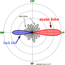
Polar plots of the horizontal cross-sections of a (virtual) Yagi-Uda antenna, with the outline marking points where the field power is 3 dB below that of an isotropic radiator.
An antenna’s radiation pattern illustrates the relative field strength of its emitted radio waves at various angles, typically depicted as a three-dimensional graph or as polar plots of horizontal and vertical cross-sections. An ideal isotropic antenna, radiating equally in all directions, would produce a spherical pattern. Nondirectional antennas like monopoles and dipoles radiate equal power horizontally, with power decreasing at higher and lower angles, forming an omnidirectional pattern resembling a torus or donut in a plot.
Many antennas exhibit a pattern with maxima, or “lobes,” at specific angles, separated by “nulls” where radiation drops to zero. This occurs due to interference between radio waves from different antenna parts, creating maxima where waves arrive in phase at distant points and nulls where they are out of phase. In directional antennas, designed to focus radio waves in a specific direction, the largest lobe, called the “main lobe,” is emphasised, while smaller “sidelobes” represent unwanted radiation. The axis through the main lobe is known as the “principal axis” or “boresight axis.”
Near Field and Far Field regions
The space surrounding an antenna can be divided into three concentric regions: the reactive near-field, the radiating near-field (Fresnel region) and the far-field (Fraunhofer) regions. These regions are useful to identify the field structure in each, although there are no precise boundaries.
In the far-field region, we are far enough from the antenna to neglect its size and shape. We can assume that the electromagnetic wave is purely a radiating plane wave (electric and magnetic fields are in phase and perpendicular to each other and to the direction of propagation). This simplifies the mathematical analysis of the radiated field.
Impedance
Electromagnetic waves passing through components of an antenna system (radio, feed line, antenna, and free space), it encounters varying impedances (e.g. E/H, V/I). At each interface, mismatched impedances cause some wave energy to reflect back to the source, creating a standing wave in the feed line. The standing wave ratio (SWR), which measures the ratio of maximum to minimum power in the wave, indicates the degree of mismatch. An SWR of 1:1 is optimal, while 1.5:1 is marginally acceptable for low-power applications where power loss is critical, and an SWR up to 6:1 may be usable with specialised equipment. Reducing impedance mismatches through impedance matching minimises SWR and maximises power transfer across the system.
An antenna’s complex impedance depends on its electrical length relative to the operating wavelength. To match the antenna’s impedance to the feed line and radio, the feed line’s impedance can be adjusted to act as an impedance transformer. More commonly, matching is achieved at the load using devices like an antenna tuner, balun, matching transformer, networks of inductors and capacitors, or matching sections such as a gamma match.
Polarisation

An antenna’s polarisation refers to the orientation of the radio wave’s electric field (E-plane) relative to the Earth’s surface, determined by the antenna’s physical structure and orientation, distinct from its directionality. For example, a straight wire antenna has different polarisations when mounted vertically versus horizontally. As a transverse wave, a radio wave’s magnetic field is perpendicular to its electric field, but by convention, “polarisation” refers to the electric field’s orientation.
Reflections can alter polarisation. In line-of-sight or ground wave propagation, horizontally or vertically polarised signals generally retain their polarisation at the receiver. Matching the receiver’s antenna polarisation to the transmitter’s significantly enhances signal strength.
Polarisation depends on an antenna’s geometry, though it may not always be obvious (e.g. quad antennas). Linear polarisation typically aligns with the direction of the antenna’s currents (as seen from the receiver). For instance, a vertically oriented whip or Wi-Fi antenna transmits and receives vertically polarised signals, while horizontally oriented antennas, like most US rooftop TV antennas, are horizontally polarised. Even in vertically oriented systems with horizontal elements (e.g. dipole arrays), polarisation aligns with the horizontal current flow. Polarisation is a critical specification for commercial antennas.
Polarisation is defined as the cumulative E-plane orientations over time, projected onto a plane perpendicular to the radio wave’s propagation direction. Generally, polarisation is elliptical, varying over time. Special cases include linear polarisation (where the ellipse becomes a line, oscillating in one direction, typically horizontal or vertical) and circular polarisation (where the ellipse’s axes are equal, with the electric field rotating around the propagation axis at the radio frequency). Circular or elliptical polarisation is classified as right-handed or left-handed using the “thumb in the direction of propagation” rule, though optical and radio engineering conventions differ.
Optimal reception occurs when the receiving antenna’s polarisation matches the transmitted wave’s. Partial matches reduce signal strength less severely than complete mismatches. A circularly polarised antenna can effectively receive both vertical and horizontal linear polarisations. However, using a circularly polarised antenna with a linearly polarised one (or vice versa) results in a 3 dB signal-to-noise ratio loss, halving the received power.
Request More Information
For further information on the range of CableFree Radio Antennas and Wireless networking products:
Please Contact Us

You must be logged in to post a comment.